

Views: 0 Author: Site Editor Publish Time: 2026-08-17 Origin: Site


Residual internal stresses in sheet metal carry a compounding cost on the fabrication floor. Microscopic deviations in flatness quickly lead to catastrophic tolerance failures during downstream laser cutting, robotic welding, and automated bending. A one-size-fits-all approach to leveling parameters consistently results in high scrap rates, edge waving, and center buckling. Different yield strengths, thicknesses, and alloys require distinct, mathematically calculated roll penetration strategies. You must match material profiles to specific CNC configurations. Establishing precise pre-operation setups ensures repeatable outcomes. Selecting the correct machine capacities helps you achieve repeatable, stress-free plastic deformation. This technical guide breaks down the exact parameters needed to process different metals effectively, eliminating operator guesswork and stabilizing your production line.
Material Yield Strength Dictates Roll Penetration: Harder materials require deeper initial bending to surpass their elastic limit and achieve permanent plastic deformation.
Entry vs. Exit Gap Ratios: Successful leveling relies on a tight entry gap for aggressive stress relief and an exit gap matching material thickness to restore absolute flatness.
Hardware Matching is Non-Negotiable: Pushing a machine beyond its intended gauge range (e.g., running thick high-tensile steel through a light-duty series) compromises roller integrity and frame rigidity.
Baseline Calibration is Prerequisite: Operational settings, tool offsets, and part coordinates are useless if the physical machine base is not perfectly leveled, trammed, and isolated from environmental vibration.
Visual flatness does not equal structural stability. The primary goal of a CNC leveling machine is the complete neutralization of internal cross-sectional stresses. When sheet metal is uncoiled or sheared, it retains memory. This memory manifests as trapped energy within the grain structure. If you cut this material without leveling it first, the trapped energy releases. The part will twist, bow, or warp out of tolerance. We measure success by how the material behaves after thermal cutting. If a laser-cut part pops up off the slat bed, the internal stresses were not neutralized.
You must bend the material past its yield point to permanently change its shape. The yield point is the elastic limit. If you bend metal below this point, it simply springs back to its original distorted shape. You must push the metal into the plastic deformation zone. However, you cannot push it so far that it reaches ultimate tensile strength. Doing so causes fractures and tearing.
When sheet metal bends, the outer radius stretches into tension while the inner radius compresses. The neutral axis in the center remains unchanged. To achieve permanent flatness, the bending force must penetrate deep enough to shift this neutral axis, forcing the entire cross-section to yield. If the force only affects the surface layers, the elastic core will pull the material back into a bow.
Higher yield strengths demand smaller roller diameters and tighter spacing. A smaller roller creates a sharper bend radius. This sharp radius forces high-strength materials past their elastic limit over a shorter distance. If you use large rollers on high-yield materials, the bend radius is too wide. The material will not yield, and the internal stresses remain trapped.
Material thickness shares an inverse relationship with required bending force. Thin materials require significantly more bending cycles over smaller rollers to yield. Thick materials require massive downward force but yield over larger radii. You must factor springback calculations into your CNC software.
Springback occurs because the core of the sheet metal remains in an elastic state while the outer surfaces enter a plastic state. When the material exits the rollers, the elastic core tries to pull the sheet back to its original shape. You must over-bend materials predictably to counteract this effect. CNC software calculates this over-bend based on the specific alloy and thickness inputted by the operator.
Leveling relies on a standard wedge-shaped roller configuration. The entry gap and exit gap perform entirely different functions. The entry rollers perform the heavy plastic deformation. You must set the entry gap significantly smaller than the material thickness. This forces the metal through a series of tight, alternating bends.
As the material moves through the machine, the roller gap gradually increases. The exit rollers taper off to exactly match the material thickness. The entry rollers break the material's memory. The middle rollers neutralize the alternating stresses. The exit rollers guide the sheet out perfectly flat. If you set the exit gap too tight, you introduce new stresses into the material right before it leaves the machine.
Operational settings cannot fix physical misalignment. You must establish a perfect mechanical baseline before powering on the equipment. A distorted machine frame transfers distortion directly to the leveling rollers. This makes accurate calibration impossible.
Your shop floor foundation dictates the machine's baseline accuracy. You must place the equipment on a solid, even floor. The concrete must meet specific load-bearing requirements to prevent sagging under the machine's weight. You must also provide a vibration-free surface. Heavy stamping presses or forklifts operating nearby cause microscopic shifts during heavy-duty processing. Isolate the machine pad to prevent external vibrations from compromising the leveling process.
Grab your dual precision levels and follow standard machinist procedures to level the machine base. Place one level parallel to the guides. Place the second level perpendicular to the guides. Adjust the machine leveling feet until both axes read zero. A perfectly planar frame is mandatory. If the frame twists even a fraction of a millimeter, the upper and lower roller cassettes will not align properly. This creates diagonal stresses in the sheet metal.
The lower roller cassette serves as the foundation plane for the entire process. Similar to leveling a CNC router spoilboard, you must perfectly tram the lower cassette relative to the machine bed. Use dial indicators to sweep the length and width of the lower rollers. If this foundational reference plane is uneven, all subsequent upper roller adjustments will fail. You cannot compensate for an un-trammed lower cassette using CNC software offsets.
Zero-point calibration establishes the mathematical relationship between the physical hardware and the software. You must zero the rollers before inputting material-specific parameters. Bring the upper and lower rollers together until they touch. Set this position as absolute zero in the control panel.
Next, input the tool offsets. These offsets account for the physical dimensions of the rollers and the mechanical play in the drive system. Accurate part coordinates depend entirely on this initial zeroing procedure. If your zero point is off by 0.1mm, your entry gap penetration calculations will be entirely wrong.
Perpendicular material feeding is non-negotiable. You must align the incoming sheet perfectly square to the entry rollers. Use precision edge guides and squaring arms. If you feed the material at an angle, you introduce diagonal stresses. Standard roller settings cannot correct diagonal warping. Misaligned entry angles cause the material to track sideways, damaging the edges and overloading the drive motors on one side of the machine.
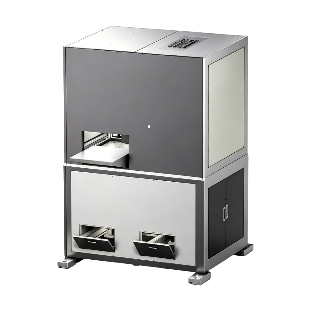
Different metals react differently to plastic deformation. You must adjust your CNC parameters based on the specific alloy, temper, and structural integrity of the sheet.
Mild steel is highly ductile. It features a predictable yield point and minimal springback. This makes it the easiest material to process on the shop floor.
Use a standard entry gap penetration. Set the entry gap 20% to 30% below the actual material thickness.
Set the exit gap to the exact nominal thickness of the sheet.
Focus on speed and throughput. Mild steel is highly forgiving of minor parameter deviations.
Run these materials at higher feed rates without risking surface tearing or motor overload.
Aluminum presents unique challenges. It has a lower yield point but is prone to rapid work-hardening. It also carries a high risk of surface marring.
Install highly polished rollers. Intermediate protective layers or specialized roller coatings prevent surface stretching and scratching.
Use a less aggressive entry gap penetration compared to steel. Over-penetrating aluminum causes micro-cracking on the surface.
Micro-adjust your settings per batch. Aluminum's memory varies wildly by temper.
For example, processing 2mm 6061-T6 aluminum requires a completely different approach than 2mm 5052-H32. The T6 temper is highly rigid and snaps if over-penetrated. You must back off the entry gap by 10% compared to the H32 temper.

High-tensile materials resist plastic deformation aggressively. They feature extreme yield strengths and massive springback.
Apply the maximum safe roll penetration at the entry point. You must force the material past its high elastic limit immediately.
Use slower feed rates. Slower speeds allow the material time to yield without overloading the machine's hydraulic or mechanical drive motors.
Processing high-tensile materials accelerates roller wear. It requires a precision metal leveling machine with superior frame rigidity.
If the frame deflects under the extreme downward pressure, the center of the sheet will not yield properly.
Perforated sheets have inconsistent cross-sectional volume. The areas with holes are weaker than the solid borders. This makes them prone to localized stretching.
Reduce the overall penetration depth. Aggressive penetration will tear the thin webs between the perforations.
Utilize specific CNC algorithms designed for perforated materials. These algorithms account for the reduced structural integrity of the sheet and apply a gentler bending curve.
Material Type | Yield Strength Profile | Entry Gap Strategy | Feed Rate | Primary Processing Risk |
|---|---|---|---|---|
Mild Steel | Predictable, Moderate | 20-30% below thickness | High | Minimal; highly forgiving |
Aluminum (Varying Tempers) | Low, Rapid Work-Hardening | Mild penetration | Medium | Surface marring, micro-cracking |
Stainless / High-Tensile | Extreme, High Springback | Maximum safe penetration | Low | Frame deflection, motor overload |
Perforated Metals | Inconsistent, Weak Webs | Reduced penetration | Medium to Low | Tearing at perforation webs |
You cannot process 10mm high-tensile steel on a machine designed for 1mm aluminum. Hardware matching is non-negotiable. Pushing a machine beyond its intended gauge range compromises roller integrity and destroys frame rigidity.
The 30 Series CNC leveling machine is engineered for thin-gauge materials. Its target application range spans from 0.5mm to 3.0mm in thickness.
This technical profile features smaller diameter rollers that are closely spaced. Small rollers create the tight bend radii necessary to effectively yield thin materials. This series is ideal for electronics components, aerospace aluminum panels, and thin-gauge copper sheets. However, it has strict limitations. It lacks the motor torque and heavy-duty frame rigidity required for high-tensile or thick-plate applications. Overloading a 30 Series machine will permanently bend the rollers.
The 40 Series CNC leveling machine serves as the versatile workhorse for general fabrication. Its target application range covers 2.0mm to 8.0mm thicknesses.
This series balances roller diameter with sufficient backing flights. The backing flights support the main rollers and prevent them from deflecting under moderate loads. It is perfectly suited for automotive stamping operations and standard sheet metal processing. The 40 Series offers the highest ROI for job shops dealing with mixed-material daily schedules. It handles both mild steel and moderate-thickness stainless steel effectively.

The 50 Series CNC leveling machine tackles heavy plate and high-strength steels. Its target application starts at 5.0mm thickness and scales upward. It processes Advanced High-Strength Steels (AHSS) and Ultra-High-Strength Steels (UHSS) with ease.
The technical profile includes massive roller diameters and extreme hydraulic or mechanical downward pressure. It features heavily reinforced backup rollers to maintain absolute rigidity. This series is built for heavy equipment manufacturing, shipbuilding, and structural steel components. In these industries, internal stress relief dictates safety and structural integrity. The 50 Series provides the brute force necessary to yield thick, stubborn materials.
Machine Series | Thickness Range | Roller Configuration | Primary Applications |
|---|---|---|---|
30 Series | 0.5mm - 3.0mm | Small diameter, tight spacing | Electronics, aerospace aluminum, thin copper |
40 Series | 2.0mm - 8.0mm | Medium diameter, standard backing | Automotive stamping, general fabrication |
50 Series | 5.0mm+ | Massive diameter, reinforced backing | Shipbuilding, heavy equipment, structural steel |
Even with the correct machine and baseline calibration, material variations cause defects. You must know how to read the metal and adjust your parameters accordingly.
Never bypass the pre-operation checks. Verify your tool offsets in the control panel. Confirm the machine levelness using your precision indicators. Check the material feed alignment with your squaring arms. Initiating the leveling sequence without these checks guarantees scrap generation. A strict checklist prevents operator errors from destroying expensive raw materials.
Edge waving looks like a ruffled pie crust along the sides of the sheet. It occurs when the edges are longer than the center. The edges have been over-stretched during previous rolling processes. To mitigate edge waving, you must stretch the center of the sheet to match the edges.
Stop the feed and reverse the material out of the rollers.
Access the CNC control panel and locate the backup flight adjustments.
Increase the pressure on the center backup flights to create a crowned roller profile.
Run a test strip to verify the center fibers have stretched to match the edges.
Center buckling, often called oil canning, is the exact opposite of edge waving. The center of the sheet is longer than the edges. The material pops up and down in the middle when pressed. To fix center buckling, you must stretch the material edges.
Halt the machine and inspect the severity of the oil canning.
Adjust the backup flights to relieve pressure on the center.
Increase pressure on the outer backup flights to create a concave roller profile.
Process a new test sheet to ensure the outer edges have elongated sufficiently.
Cross-bow is a curve across the width of the sheet. Coil set is a curve along the length of the sheet. Both defects indicate that the material retains its original memory from the steel mill. The cause is always insufficient entry penetration. The metal never reached its yield point.
Decrease the entry gap to force the material into deeper plastic deformation.
Break the material's memory at the very first set of rollers.
Verify your exit gap remains set to the exact material thickness to guide it out flat.
Manual tweaking introduces massive inconsistency. Relying on an operator's feel leads to varying results across different shifts. Advocate for strict CNC preset utilization. When you achieve perfect flatness for a specific batch of material, save those exact parameters into the CNC memory. This ensures repeatable outcomes regardless of which operator runs the machine. Lock the parameters to prevent unauthorized adjustments.
Audit your current material inventory to determine your average and maximum yield strengths before selecting a machine series.
Verify your shop floor foundation meets the strict vibration isolation requirements for precision equipment installation.
Conduct a physical material test run with the manufacturer using your specific, hardest-to-level alloys to validate machine capability.
Establish a standardized, mandatory zero-point calibration schedule for all operators to maintain baseline accuracy.
A: The ideal setting depends entirely on the material's yield strength and thickness. Generally, operators set the entry gap 20% to 30% tighter than the material thickness to force plastic deformation. The exit gap must match the material's nominal thickness exactly. This ensures the sheet exits completely flat without introducing new stresses at the end of the cycle.
A: Material thickness dictates the required bending force and roller diameter. Thinner materials require smaller rollers spaced closely together to achieve a tight bend radius that yields the metal. Thicker materials demand massive downward force and larger rollers to prevent equipment damage while bending. You must match the machine's gauge capacity to your material thickness.
A: A stable floor prevents the machine frame from twisting under heavy loads. If the floor sags or vibrates, the machine base distorts. This distortion transfers directly to the leveling rollers, causing diagonal misalignment. Accurate calibration is impossible if the foundation shifts during heavy-duty processing.
A: Roller offsets are mathematical values entered into the CNC software to account for the physical dimensions of the rollers and mechanical play in the gears. Accurate offsets ensure the software's calculated gap exactly matches the physical gap. Incorrect offsets lead to over-penetration or under-penetration, resulting in scrapped parts.
A: It depends on the machine's capacity and the material thickness. While versatile machines exist, stainless steel requires immense force and rigid frames. Aluminum requires polished rollers and gentle handling to prevent surface marring. Processing thick stainless on a machine calibrated for thin aluminum will permanently damage the rollers.
A: Edge waving means the edges are stretched longer than the center. To fix it, you must stretch the center to match. Adjust the machine's backup flights to crown the rollers. This applies more downward pressure to the center of the sheet, elongating the center fibers until the lengths equalize.

