

Views: 0 Author: Site Editor Publish Time: 2026-07-01 Origin: Site


Flatness defects like coil set, crossbow, and edge waves constantly plague metal fabrication. These imperfections directly cause costly downstream manufacturing failures in automated laser cutting, robotic welding, and high-speed stamping operations. You cannot simply press metal flat and expect it to stay there. A hydraulic leveling machine does not just flatten metal visually. It fundamentally resets the internal stress of the material through calculated plastic deformation. By aggressively bending the metal back and forth, the equipment essentially erases structural memory.
For procurement and engineering teams, understanding these exact mechanical realities is critical. You must size equipment correctly to avoid catastrophic bottlenecks. Mastering hydraulic leveling ensures precise, repeatable yield rates across your entire production line. In this guide, we will explore the physics, core components, and configuration strategies you need to specify the right system for your facility.
Hydraulic leveling relies on alternating bending cycles to push material past its yield point and eliminate internal stresses.
Hydraulic cylinders provide real-time gap control and overload protection, outperforming traditional mechanical levelers in consistency.
Roll configuration (e.g., 30-roll vs. 40-roll) dictates the precision and minimum thickness capabilities of the machine.
Sizing a machine requires strict evaluation of maximum yield strength, material width, and gauge range to prevent catastrophic roll deflection.
To understand leveling, you must distinguish between plastic and elastic deformation. When you bend a piece of metal slightly, it springs right back to its original shape. Engineers call this the elastic zone. To achieve permanent flatness, the machine must push the material beyond this elastic limit. It must enter the plastic zone. Once metal crosses its yield point, it undergoes permanent structural changes. It stops springing back. This core principle governs every modern leveling operation.
The machine achieves this permanent state through an alternating bending process. As material enters the system, it passes through an offset configuration of upper and lower rollers. The initial entry rollers apply highly aggressive bends. These deep bends shatter the material's original memory. They stretch the metal fibers past their yield point. As the material progresses toward the exit, the rollers gradually reduce their bending amplitude. The final rollers apply very shallow bends. This progressive reduction leaves the material perfectly flat and deeply stress-relieved. Metallurgists often refer to this stress equalization phenomenon as the Bauschinger effect.
Hydraulics play an indispensable role in this physical process. Coiled metal rarely features uniform hardness. You will frequently encounter localized hard spots along a single coil. Mechanical systems struggle here. They either stall or apply uneven pressure. Hydraulic systems operate differently. They maintain consistent pressure across varying material densities. They dynamically adjust to hold the required deformation curve. This fluid responsiveness ensures you eliminate internal stress evenly across the entire sheet.
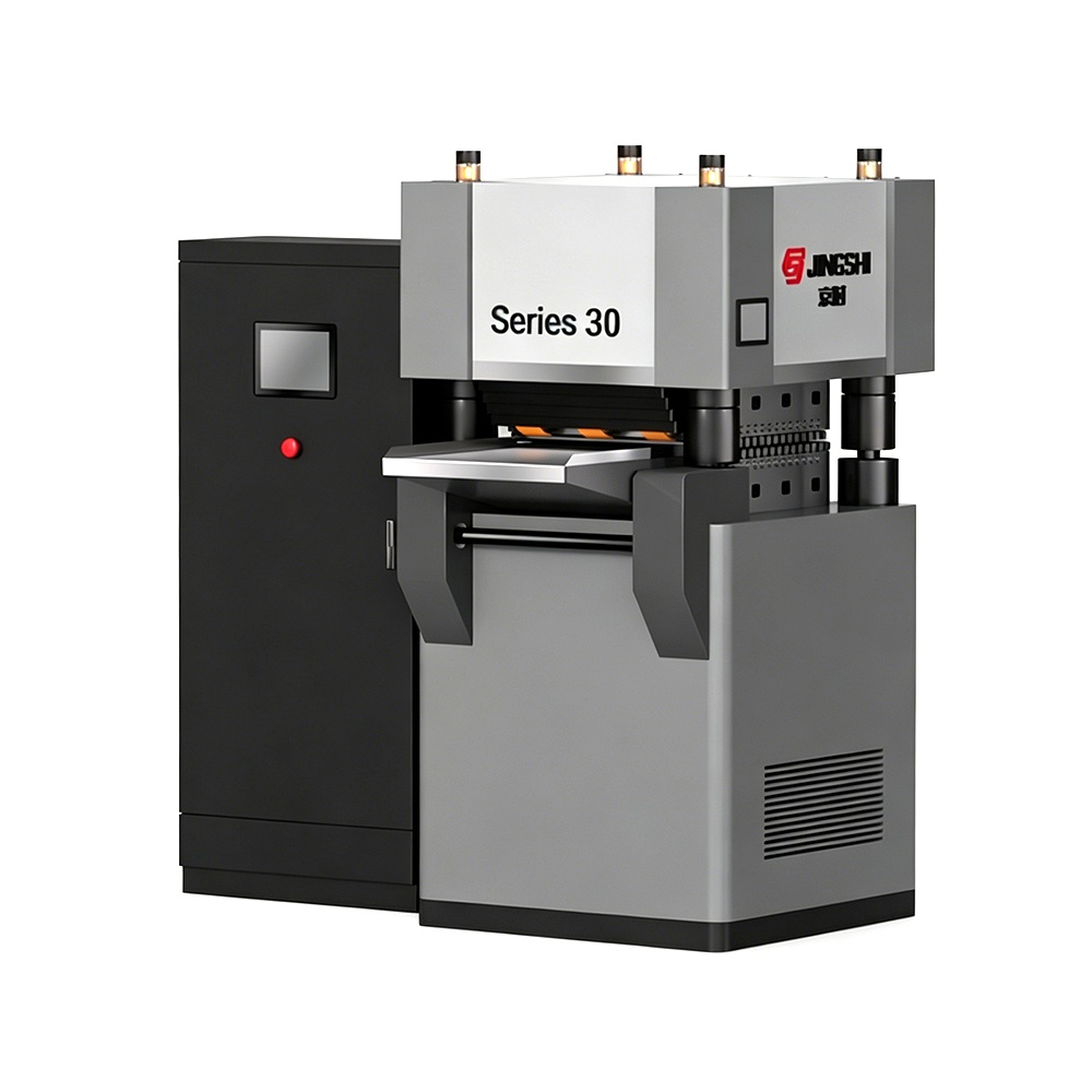
Evaluating a hydraulic sheet leveler requires looking past the exterior frame. The internal anatomy dictates the machine's true capabilities. You must examine four primary subsystems to understand how the equipment achieves tight tolerances.
Main Leveling Rolls (Work Rolls): These are the direct contact points interacting with your material. Roll diameter, surface hardening, and spacing matter immensely. Smaller diameters bend thinner materials more effectively. Manufacturers typically harden these rolls to withstand immense friction and prevent surface scoring. Spacing depends directly on the material gauge you intend to process.
Backup Rollers: Work rolls cannot operate alone under extreme pressure. They will deflect or bow. Backup rollers sit directly behind the work rolls. They provide rigid, unyielding support. They prevent the work rolls from bending under massive loads. This structural reinforcement ensures uniform flatness across the entire width of your material.
Hydraulic Cylinder Network: Precision requires micro-millimeter adjustments. Heavy-duty hydraulic cylinders control the roll gap. This gap dictates the exact penetration depth of the work rolls into the material. Advanced sensor networks monitor this gap continuously. The cylinders adjust instantly to maintain exact positioning under varying forces.
Overload Protection System: Operators sometimes feed oversized or excessively hard material into the machine. This triggers a critical safety feature. Hydraulic pressure valves detect the abnormal load immediately. They automatically release the pressure and open the roll gap. This prevents catastrophic mechanical fractures and saves your work rolls from permanent ruin.
Understanding this anatomy helps you spot structural weaknesses during the procurement process. A machine might boast high pressure ratings, but weak backup rollers will still result in edge waves.

The total number of rolls inside your machine dictates its processing sweet spot. You must follow a strict core rule. Thinner, higher-precision materials require smaller roll diameters and a higher number of rolls. Thicker, heavier plates require larger roll diameters and fewer rolls. You cannot buy one machine to perfectly level everything from thin foil to thick armor plate.
A 30-roll hydraulic leveling machine represents a highly specialized configuration. It delivers an exceptional number of alternating bending cycles. This high cycle count aggressively works thinner substrates. It is ideal for specific thin-gauge processing, electronics manufacturing, or fine precision stamping. When evaluating this setup, you must acknowledge its trade-offs. It delivers superior flatness on delicate metals. However, the small diameter rolls lack the sheer structural rigidity needed for heavy steel plate. Pushing thick material through a 30-roll setup will destroy the work rolls.
Conversely, a 40-roll hydraulic leveling machine pushes precision boundaries even further. Manufacturers design these for ultra-high precision environments. You will often see them built as specialized multi-stage leveling cassettes. They handle zero-tolerance flatness requirements flawlessly. Aerospace contractors and delicate foil manufacturers rely on them heavily. As an evaluative lens, you must justify the higher capital expenditure here. Only specify a 40-roll system if your operational needs absolutely demand microscopic flatness tolerances.

Processing high-strength steels (HSS) and thick plates requires immense force. A standard mechanical system uses motorized worm gears and heavy screw jacks to set the roll gap. This older technology struggles under modern industrial demands. A true heavy duty leveling machine relies entirely on hydraulic force. Hydraulic cylinders deliver instantaneous, unyielding pressure. They easily process high tensile strength materials that would stall a mechanical gearbox.
Dynamic gap control clearly highlights the hydraulic advantage. Mechanical systems require rigid screw stops. If the material thickness varies slightly, the mechanical gap remains static. This leads to inconsistent leveling. Hydraulic systems operate dynamically. They use sensitive position sensors and fast-acting servo-valves. They adjust the roll gap in milliseconds while under full load. This ensures the leveling curve remains perfect, regardless of minor material inconsistencies.
Maintenance and uptime realities further separate the two technologies. Mechanical screw-jacks experience extreme friction under load. If material jams, mechanical systems often lock up entirely. Freeing a jammed mechanical leveler requires hours of dangerous manual labor. Hydraulics offer inherent self-lubricating properties. More importantly, they offer simple overload recovery. If a severe jam occurs, the operator simply hits a button. The hydraulic frame lifts instantly, clearing the jam in seconds. This drastically reduces costly operational downtime.
Mechanical vs. Hydraulic Leveling Systems Comparison
Feature / Capability | Mechanical Leveler (Screw-Jack) | Hydraulic Leveler (Cylinder) |
|---|---|---|
Gap Adjustment | Static; requires manual or motorized screw turns. | Dynamic; uses sensors and servo-valves under load. |
Overload Protection | Prone to mechanical locking or fractured gears. | Automatic pressure relief valves open gap instantly. |
Jam Clearance | Labor-intensive; high downtime risk. | Push-button frame lift; minimal downtime. |
High-Strength Steel Capability | Struggles with material hard spots; high deflection risk. | Easily maintains pressure curves across hard spots. |
Procuring the right machine requires strict technical evaluation. You must move beyond the basic expectation that "it makes metal flat." You need to define measurable success criteria. Ask engineering what specific tolerances they require for downstream processes. A common benchmark for precision fabrication is achieving $\leq 0.5mm/m$ flatness. If your machine cannot hit this metric consistently, robotic welders and laser cutters will experience tracking errors.
Material sizing limits represent the most common procurement pitfall. Buyers frequently cross-reference maximum width and maximum thickness. They routinely forget maximum yield strength. This oversight destroys machines. A machine rated for 10mm mild steel will fail spectacularly if you feed it 10mm advanced high-strength steel. You must map the exact metallurgical properties of your hardest materials against the machine's absolute maximum load capacity.
You must also anticipate implementation and facility risks. Heavy-duty hydraulic presses generate massive downward forces and vibrations. Standard factory floors often crack under this stress. You will likely need specialized concrete foundation pits. Furthermore, operator training curves deserve attention. Advanced CNC hydraulic control systems eliminate manual guesswork, but they require digital literacy. Your operators must transition from turning mechanical hand-wheels to programming material profiles into a touchscreen interface.
As a next-step action, never buy a machine based purely on a brochure. Request a proof-of-concept (POC) material test from the OEM before finalizing any shortlist. Send them a sample of your worst, most heavily warped coil. Demand they run it through their proposed machine configuration. Verify the final flatness tolerance yourself.
Hydraulic leveling is a highly precise, measurable process of controlled deformation. It does not rely on brute force. It relies on advanced physics, calculated yield points, and responsive fluid dynamics. You neutralize internal material stress by strategically bending metal back and forth through a specifically engineered roll configuration.
When you evaluate systems, advise your team to prioritize structural integrity over superficial software features. Rigid backup roll structures and highly responsive hydraulic gap controls dictate your true flatness capabilities. A flashy touchscreen cannot compensate for weak work rolls deflecting under heavy loads.
Take action today by auditing your current flatness defects. Document your most difficult material specifications, including thickness, width, and yield strength. Submit these exact metrics to a qualified manufacturer for a customized equipment evaluation or a proof-of-concept test run.
A: Hydraulic machines detect excessive pressure instantly. They trigger an automatic overload relief valve. This valve immediately opens the roll gap, safely aborting the process and preventing internal damage. Conversely, mechanical machines lack this fluid bypass. Feeding oversized material into a mechanical system often results in permanently bent work rolls, shattered backup bearings, or entirely broken gearboxes.
A: Yes. Advanced machines utilize adjustable backup rolls located behind the work rolls. Operators can independently adjust these backup flights. This strategically bends the work rolls themselves, applying highly targeted pressure to specific zones of the metal. This targeted stretching elongates the shorter fibers of the material, neutralizing edge waves and center buckles effectively.
A: These terms indicate the internal layers of backup and intermediate rolls. A 4-high setup features standard work rolls and backup rolls for structural leveling. A 6-high setup adds intermediate rolls between the work rolls and backups. You choose 6-high configurations to prevent surface marring on highly sensitive, polished materials like aluminum or bright stainless steel.

